Process-based, procedural or CAD-rendered synthetic defects?
Procedural defects are drawn from rules, CAD-rendered defects are rendered from a 3D model of the part, and process-based defects are generated from a photograph of a good part, following how it is made. Visynex is process-based, and works from one photo. There are three common ways to make synthetic images of defects for training an inspection model. They differ in what they need from you, in how the label is made, and in where the image can look wrong. This page sets them side by side, in general terms, then says which one Visynex is.
What Visynex isVisynex makes synthetic defect images for training machine vision inspection models. Each image is made from one photograph of a good part, and every defect image ships only if a separate detection pass finds the defect ordered.
The three approaches, in general terms
These are general descriptions, not measurements of ours. Results vary a great deal by part, camera and method.
- Procedural. A program draws the defect from rules: a scratch as a line with a chosen width and depth, a spot as a blob of a chosen colour, a crack as a branching path. The drawn defect is then blended onto images of good parts. Because the program decides where the defect goes, it knows the exact outline, so every label is exact. It is cheap to run. Each defect type needs its own rules, and a defect only looks as real as those rules allow.
- CAD-rendered. A 3D model of the part is given materials and lights and rendered, usually on graphics processors, with defects modelled into the geometry or the surface. The renderer knows every pixel, so labels are exact, outlines included, and the camera, pose and lighting can be set to anything. It needs a CAD model of the part, time to set up materials and lighting, and rendering hardware. Rendered images can differ from the camera’s images in small ways (texture, reflections, noise) that a model may learn.
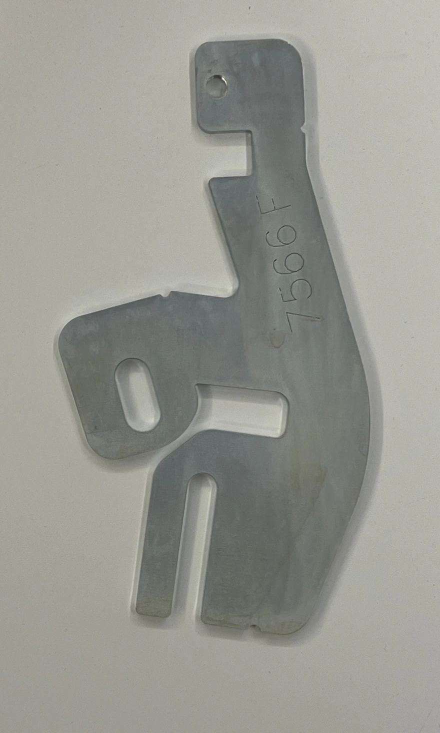
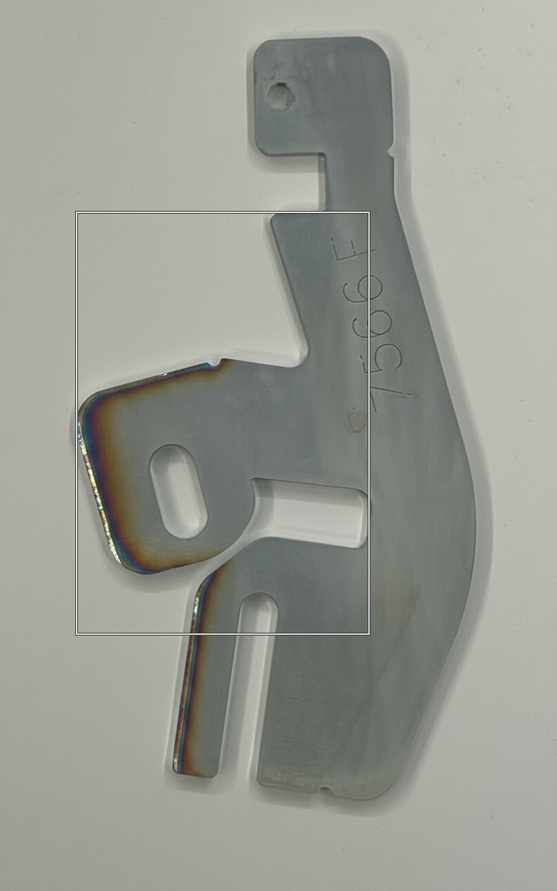
- Process-based. The defects come from how the part is made. The manufacturing process is worked out first, and the defect classes follow from it: dross and heat tint for a laser-cut edge, porosity and inclusions for a casting. The images are generated from a photograph of a good part, so they keep that part’s real surface and your camera’s look. The generator does not know the exact outline of what it made, so the label has to come from somewhere else.
What each one needs from you
| Procedural | CAD-rendered | Process-based (Visynex) | |
|---|---|---|---|
| Input | images of good parts, and rules for each defect | a CAD model, materials, lighting | one photograph of a good part |
| Defect samples needed | no | no | no |
| Where the label comes from | the program that drew it | the renderer | a detection pass on the finished image |
| Label type | exact outline or box | exact outline or box | a box |
| Pose and lighting | those of your good images | anything you set | your photograph’s |
| Where it can look wrong | the rules are simpler than real defects | rendered surfaces are not camera images | the generated defect may not be the one you ordered |
Which one is Visynex
The Visynex Synthesis Engine is process-based.
- The input is one photograph of a good part. No defect sample goes into it.
- The defect classes come from the manufacturing process: the one you tell us, or, if you’re not sure, the one inferred from that photograph, rather than a generic list. They’re the starting point for the classes we propose for your part, not a fixed menu.
- Each image with a defect is looked at again after it is made. A detection pass runs on the finished image, side by side with your reference photograph. The box you receive comes from that pass.
- If the defect you ordered is not found in the image, the image is withheld.
- What the label tells you is exactly this: the defect you ordered was detected in that image, and the box is where it was found. It is not a search for other changes.
- The output is a supervised dataset: images with a box per defect, in YOLO and COCO format, plus defect-free images with empty labels.
When each one tends to fit
Again general guidance, and a starting point rather than a rule:
- Procedural tends to fit when the defects are simple shapes on a plain surface, and when you need a very large number of images with exact outlines.
- CAD-rendered tends to fit when you already have the CAD model and the people to set up materials, and when you need poses or lighting your line has not photographed.
- Process-based tends to fit when you have a good part and a camera but no CAD model and no defect samples, and you need boxes in YOLO or COCO format for a supervised detector.
What none of them can show
Dimensional errors, internal flaws, and anything on a face the camera doesn’t see. If your rejects are mostly measured with a gauge, synthetic images are not the right tool for those classes, and we’ll tell you.
Questions
What is the difference between procedural, CAD-rendered and process-based synthetic defects?
Procedural defects are drawn by a program from rules and blended onto images of good parts. CAD-rendered defects are modelled into a 3D model of the part, which is then rendered. Process-based defects come from how the part is made, and are generated from a photograph of a good part.
Which approach works from one photo?
Process-based, as the Visynex Synthesis Engine does it: the input is one photograph of a good part, and no defect sample goes into it. Procedural needs images of good parts and rules for each defect. CAD-rendered needs a CAD model, materials and lighting.
Do I need a CAD model?
Not for the process-based approach. CAD-rendered images need one, plus time to set up materials and lighting, and rendering hardware.
Which approach gives exact outlines?
Procedural and CAD-rendered: the program or the renderer knows where it put the defect, so the outline is exact. A process-based generator does not know the exact outline of what it made, so its label is a box from a detection pass on the finished image.
Can I use process-based images for automated optical inspection (AOI)?
As training data: the images and their YOLO and COCO labels are for training the inspection model of an automated optical inspection (AOI) system or any other machine vision inspection. We supply the training images, not the inspection system.
What can none of them show?
Dimensional errors, internal flaws, and anything on a face the camera doesn’t see. If your rejects are mostly measured with a gauge, synthetic images are not the right tool for those classes, and we’ll tell you.
Tell us how your part is made.
Try it on your own part
Sign in with your work email, upload one photograph of a good part, and get up to 10 images of it back, labelled in YOLO and COCO. Each takes about a minute. Free, once per email address.
Try it freeTalk to an engineer
Thirty minutes with someone who built the pipeline. No upload, no account.
Book a call